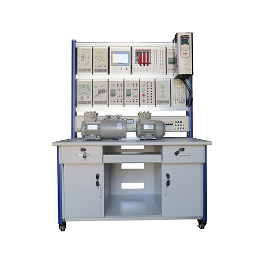
PGP-1 Integrated System Of Generation-Propulsion (Electric Generation) Didactic Equipment Electrical Training Panel
Example of an Integrated System of Generation-Propulsion: description of the electrical installation of an oil rig; Electrical installations in hazardous areas with risk of explosion and Electric power generation. TRAINING PROGRAM: • Example of an Integrated System of Generation-Propulsion:description of the electrical installation of an oil rig. • Electrical installations in hazardous areas with risk of explosion • Electric power generation: - motor-alternator sets used in the Integrated Systems ofGeneration-Propulsion - study of 3-phase brushless alternators - devices for controlling and regulating the output voltage - devices for controlling and regulating the reactive power and sharing of this power when the machines run in parallel - electronic relay for protection against overloads. Settingthe relay parameters - electronic relay for protection against the max/min limits ofthe output voltage. Setting therelay parameters. Relationwith alternator excitation - electronic relay for protection against the max/min limitsof the frequency of output voltage. Setting the relayparameters. Relation with the RPM of the prime mover - electronic relay for protection against the wrong threephase circuit sequence, missing phase and phaseunbalance. Setting the relay parameters - action of the aforesaid safety devices on the main switch ofM-G set - parallel procedure of alternators - instrument for measuring and optimizing the % value of the(active) power consumed versus the total available poweron the bars. Utility and programming of this instrument - display of the output waveforms on the oscilloscope; effectof the different types of load - harmonic analysis of voltage and current versus thedifferent types of load - study of 3-ph transformer in no-load and load conditions(transformer and load supplied separately) TECHNICAL CHARACTERISTICS: CONTROL PANEL OF THE GENERATION SECTION • vertical panel wholly wired with components of industrialtype • fore side with devices and connections marked with theirinternational symbols • all connections are carried out exclusively via safetyterminals, leads and jumpers with plugs of 4 mm • multi-pole connectors for connecting prime movers andalternators are placed at the sides of the panel • mushroom-head emergency pushbutton with mechanicalholding.The control panel includes: • 2 microprocessor-controlled drives for the motors (primemovers), with possibility of selecting operational modes:V/f or vector, and of modifying ramp times, ON-OFF switch,potentiometer for speed control and stand-by switch. • 2 Automatic Voltage Regulators (AVR) for the 3-ph alternator,with potentiometer for adjusting the output voltage • 2 RPS (Reactive Power Sharing) for the 3-ph alternatoroperating in parallel • 2 microprocessor-controlled multi-function instruments (onefor each alternator), for measuring frequency, voltage (up to850 V), current (up to 10 A), active, reactive and apparentpower, phase and 3-ph. power factor, and for harmonicanalysis of output energy. It is provided with communicationRS485 port for data acquisition via PC (not included), andconnections are carried out via safety terminals for plugswith diameter of 4 mm. They are provided with display toshow up to 4 electric parameters chosenby the user, simultaneously. Possibilityof connection with other similarinstruments in LAN • 2 protection relays for control of min/max voltage, min/max frequency,correct phase presence, asymmetryand phase sequence, in the range 380-440 V 50-60 Hz. Regulation of voltagethreshold Un between 80 and 115%, offrequency threshold f between ±1 and 10 % with delay time between 0.1 and20 s, instantaneous intervention forwrongsequence or missing phase andwith asymmetry over 30%. An exchangecontact will signal abnormal condition,with automatic reset when normalconditions are restored • 2 automatic switches with fi xed magnetic threshold andadjustable thermal relay for protection of alternator againstoverload and short-circuit. • 2 contactors for the parallel, with START/STOP pushbuttonsand selector for starting the automatic parallel procedure. • 1 double vertical voltmeter of 500 Vac + 1 double verticalfrequency-meter of 45-65 Hz - 500 Vac for the parallel • 1 electronic microprocessor-controlled synchronoscope,with relay of consensus for the automatic parallel. Thisinstrument has some LEDs (18 LEDs, 2 colors) to indicatelead-lag and coincidence of the two 3-ph voltage circuits.Adjustment between 1 and 10 % of difference of twovoltages, or between 2 and 20 degrees of difference of thetwo 3-ph voltage circuits; the delay time for closing the relayis selectable between 1 and 10 s • 3 fi lament lamps of 400 V - 5 W for signaling the sequence ofthree-phase voltage circuits and helping the parallel • 1 selector for connecting the instruments for parallelbetween bus-bars and alternators • 1 digital instrument for showing the % value of theinstantaneous absorbed power versus the power availableon bus bars. This instrument includes 2 LEDs to indicatewhich and how many generators are connected with thebus bars (available power), another LED that blinks whenload exceeds 80% of the available power, pushbuttons todisplay and program the values of the involved powers. A3-ph active power converter for unbalanced loads will detectthe instantaneous consumed power and sends its data tothe instrument for % comparison. • 1 general 4-pole magneto-thermal automatic switch withmin.-voltage releasing coil, voltage pilot lamp • 1 mushroom-head emergency pushbutton with mechanicalholding. • 2 universal single-ph 2-pin sockets Unel 230 V - 10, 16 A, forpowering various apparatuses. Power supply for the complete system mod. PGP-1:3 x 400 V - 50 Hz - 10 kVA(other voltage and frequency on demand) Dimensions of the panel: 1340 x 660 x 830 mm Net weight: 73 kg Supply with THEORETICAL – EXPERIMENTAL HANDBOOK